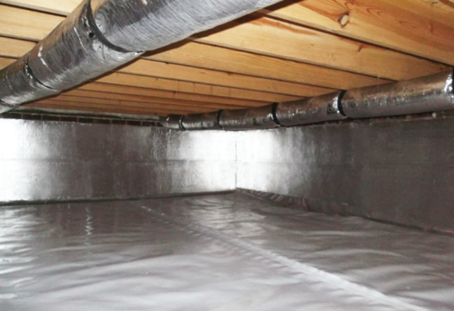
Crawl spaces behave differently than any other part of a building. They collect ground moisture, experience wide temperature swings, and influence how the floors above feel from season to season.

Every foundation interacts with temperature, moisture, and soil movement. When frost drives deep into the ground, expanding water lifts the structure above, an effect known as frost heave. Frost-protected shallow foundations (FPSF) avoid that risk by using continuous energy efficient insulation around and beneath the slab to stabilize soil temperature and prevent movement.
Every building loses energy somewhere. Heat moves through framing, ceilings, and joints faster than most owners realize, driving up utility costs and carbon emissions. Installing energy efficient insulation is the single most effective way to control that loss, and in practical terms, it’s where measurable savings start.
Every building envelope leaks under pressure. When those boundaries allow uncontrolled airflow, efficiency, comfort, and durability all decline. Properly air sealing exterior walls prevents air movement through framing joints, penetrations, and sheathing seams—issues that otherwise lead to energy loss and hidden moisture damage
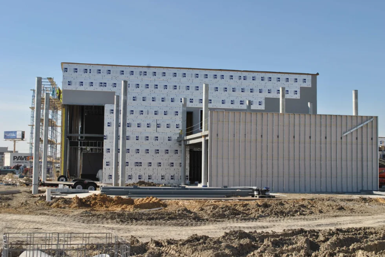
Every exterior wall protects a structure from the elements and prevents fire from spreading between buildings. The International Building Code (IBC) defines the fire rated wall requirements that specify the duration of fire resistance, minimum property-line distance, and limits on openings. Understanding these parameters helps ensure the building envelope remains safe, efficient, and inspection-ready.
An exterior wall’s rating measures how long it can resist heat, flame, and structural failure—typically one to four hours depending on construction type and distance from adjacent property.
Fire resistance is verified through ASTM E119 or UL 263 (IBC §703.2), both of which establish how assemblies are tested for structural endurance, temperature rise, and flame passage. Section 705 connects that performance rating to fire-separation distance (FSD)—the space between an exterior wall and the nearest lot line, public way, or another building. The smaller the distance, the higher the required protection (§705.5). These core definitions establish the foundation for all fire rated wall requirements in the IBC.
The IBC framework establishes how construction type and occupancy group determine each building’s required fire-resistance performance before the wall rating tables come into play.
The IBC first classifies a building by construction type and occupancy group before assigning minimum fire-resistance ratings. Types I and II use non-combustible materials such as concrete and steel, while Types III–V allow controlled amounts of combustibles. Occupancy groups—Assembly, Business, Educational, Industrial, Mercantile, Residential, Storage, and Utility—define how spaces are used and the associated risk.
Table 601 lists required ratings for structural elements, and Table 602 applies those principles to exterior walls, assigning hourly ratings based on fire-separation distance and exposure side. Together, they define the baseline fire rated wall requirements that determine how each wall must perform under fire exposure.
The fire-separation distance (FSD) determines how an exterior wall must perform when exposed to potential fire from a neighboring structure. It’s measured perpendicularly from the wall’s exterior face to the nearest property line, public way, or imaginary lot line separating buildings on the same site (IBC §202).
FSD at a glance:
10 ft or less → Wall must resist fire from both sides
Greater than 10 ft → Exposure from interior side only (§705.5)
Walls located within 10 ft (3 048 mm) of a property line fall into the high-risk zone for radiant heat and flame contact and must be rated for two-sided exposure. Beyond 10 ft, only the interior side is evaluated. Identifying this threshold during design allows teams to plan setbacks, glazing, and insulation early while staying within the IBC’s fire rated wall requirements.
Once the fire-separation distance is determined, the next step is to verify the required hourly rating using the IBC reference tables. These tables define minimum performance expectations for both structural and exterior-wall assemblies.
Table 601 establishes ratings for the building’s primary structural frame, while Table 602 applies those requirements to exterior walls based on construction type and fire-separation distance. In a typical Type IIA business occupancy, a non-bearing exterior wall may require a one-hour rating when the fire-separation distance is 30 ft (≈ 9 m) or more, but two hours when it’s less than 30 ft.
The exact value depends on occupancy, construction type, and any local amendments, so the project’s jurisdictional Table 602 must always be consulted. Each component—structure, insulation, joints, and fasteners—must achieve the required rating within a tested ASTM E119 or UL 263 assembly. Confirming that alignment during design simplifies plan review and prevents rework later.
IBC §705.8 limits unprotected and protected openings—windows, doors, and vents—based on fire-separation distance and sprinkler coverage. At 3 ft (≈ 0.9 m), unprotected glazing is typically prohibited; at 15 ft (≈ 4.6 m), larger protected windows are often permitted within limits.
Only NFPA 13 sprinkler systems (per §903.3.1.1) qualify for opening-area increases—NFPA 13R systems do not. These distinctions affect façade layout and must be confirmed early in design to avoid conflicts between architectural intent and fire-protection strategy. Final allowable opening percentages must always be verified directly in Table 705.8. Coordinating closely with fire-protection engineers ensures glazing and insulation details align with both Table 705.8 and the project’s overall fire rated wall requirements.
Even when wall materials meet fire-resistance standards, the performance of the entire assembly depends on how every joint, fastener, and penetration is detailed and sealed during construction.
IBC §§714 and 715 require each joint and penetration to maintain the tested fire-resistance rating through the wall’s full thickness. Fire-resistive joint systems prevent heat and flame from traveling through movement joints, while approved fire-stopping materials close gaps around pipes, conduits, and ducts.
These systems are tested under ASTM E1966 / UL 2079 for joints and ASTM E814 / UL 1479 for penetrations. Substituting or omitting any listed component can void the rating and trigger rework. Consistent coordination between designers, contractors, and inspectors ensures that every layer—from sheathing and insulation to sealant—matches its tested listing and that the wall functions as a complete, code-compliant fire barrier.
Adequate Separation (20 ft) – A Type IIA office wall 20 ft from the lot line typically requires a one-hour interior-side rating (§705.5). Glazing may be generous if it meets Table 705.8 limits.
Reduced Separation (8 ft) – At 8 ft, exposure applies to both sides, requiring a two-hour rating. Unprotected windows are prohibited unless tested as protected assemblies (§705.8.2).
These examples illustrate how small distance changes can alter required fire resistance under IBC fire rated wall requirements.

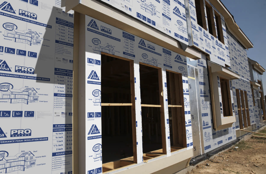
Exterior wall design must balance structural integrity, energy efficiency, and fire safety. High-performance polyisocyanurate (polyiso) insulation supports all three by delivering high R-value per inch within assemblies that have been tested for fire exposure.
Polyiso combines high thermal resistance with proven fire performance, allowing it to serve as both insulation and part of a rated barrier system. Its closed-cell structure limits flame spread and smoke development, helping assemblies meet the hourly ratings established in IBC Tables 601 and 602. When integrated into a listed design, it supports continuous insulation without compromising fire-resistance or moisture management.
Under the 2021 IBC, exterior wall assemblies in Types I–IV construction that include combustible components—such as cladding, air barriers, or foam plastics—must comply with NFPA 285 (§2603.5.5; Chapters 14 and 26). NFPA 285 measures flame spread and heat propagation within full-scale wall assemblies. Using polyiso insulation listed within an NFPA 285-tested design satisfies these requirements while preserving the wall’s rating from Table 602.
Rmax polyiso insulation is tested within compliant assemblies that meet these fire-propagation limits while maintaining high thermal efficiency. When installed as part of a tested configuration, continuous polyiso insulation supports IECC energy goals and the IBC’s fire rated wall requirements simultaneously, linking thermal and fire performance in one code-compliant system.
Even the best wall design can fail inspection if documentation and installation don’t match the tested configuration. Every rated exterior-wall assembly must be verified, referenced, and recorded from design through completion to confirm full code compliance.
Accurate documentation begins with submittals that cite the UL design number or ASTM E119 / UL 263 assembly establishing the wall’s fire-resistance rating (IBC §703.2, §703.2.2). Each layer—sheathing, insulation, joints, and fasteners—must correspond to that tested configuration.
If openings or penetrations are relocated, the design team must re-evaluate the assembly under the same test standard to confirm the rating still holds.
Surface coatings or patch materials cannot establish or restore a tested rating under §703.2—only approved fire-stop systems can.
Thorough recordkeeping, photographic documentation, and pre-closeout verification help plan reviewers and inspectors confirm that every wall performs exactly as tested, minimizing delays during final approval.
Energy and fire performance work together. Continuous insulation required by the IECC and ASHRAE 90.1 must also meet the IBC’s fire rated wall requirements.
Coordinating both objectives within a single tested assembly avoids conflicts between thermal targets and fire-safety obligations. Polyiso provides exceptional thermal resistance while maintaining proven fire performance, enabling design teams to achieve energy efficiency and code compliance simultaneously. When these requirements are addressed through a unified assembly approach, the wall system maintains both thermal continuity and fire integrity throughout the building envelope.
Identify construction type and occupancy (Tables 601 & 602).
Measure FSD (§202).
Determine exposure side(s) (§705.5).
Apply Tables 601 & 602 for required rating.
Verify openings (Table 705.8).
Select UL / ASTM-listed assemblies meeting fire + energy criteria.
Document listings and inspection records.
Following these steps provides traceable compliance and minimizes redesign delays.
Rmax engineers and manufactures polyiso insulation systems tested for rated exterior-wall assemblies. Each solution is evaluated for fire resistance, moisture protection, and thermal performance to meet modern code requirements. Contact our technical team today for project-specific guidance and tested-assembly documentation.
Cold walls on the job mean lost energy and comfort once the building’s in use. A passive house wall assembly eliminates those losses by maintaining airtight, thermally continuous layers through every transition. When insulation, air sealing, and vapor control align, the structure performs predictably in any climate and under any load.
Passive House certification rests on hard numbers, not good intentions. Typical wall assemblies target a U-value between 0.10 and 0.15 W/m²·K—roughly R-38 to R-60 depending on climate. Airtightness can’t exceed 0.6 air changes per hour at 50 pascals (n₅₀ ≤ 0.6 ACH₅₀), and every thermal bridge has to be addressed through a passive house wall assembly designed for continuous insulation.
PHPP (Passive House Planning Package) modeling keeps designers honest. Each layer’s thermal resistance and vapor characteristics feed into that calculation, and even a pencil-thin gap can throw off the heat-loss numbers more than you’d think. That’s why airtightness and alignment checks start long before the first blower-door test.
Every high-performance wall manages four control layers: water, air, vapor, and thermal. Their sequence decides whether the wall dries, sweats, or lasts for decades.
The outer layer sheds bulk water while still allowing limited vapor diffusion. The air barrier—often a taped sheathing panel or integrated membrane—forms the pressure boundary that hits n₅₀ ≤ 0.6. These layers protect structure and insulation from external moisture while controlling infiltration that drives up heating and cooling loads.
Vapor control shifts with climate. In cold regions, vapor retarders move to the interior to stop indoor humidity from condensing within the wall. In mixed or warm zones, systems stay vapor-open to allow outward drying and prevent trapped moisture. Placement and permeability must match climate data to keep materials above their dew point and assemblies dry over time.
Thermal control comes from placing continuous insulation where it belongs—outside the air and vapor layers. Polyiso boards such as Rmax Thermasheath® or ECOMAXci® deliver high R-value per inch, so walls remain thinner without losing performance. This configuration keeps sheathing warm, eliminates thermal bridging, and ensures the passive house wall assembly maintains full continuity through every transition.
Passive House design leaves room for method, but not for leaks. Builders and architects pick assemblies that hit targets while fitting regional materials and labor skills.
Double-stud walls are familiar and forgiving. Two stud frames with a gap hold dense-pack cellulose or blown fiberglass for deep insulation. Still, the design needs careful moisture control—once vapor gets trapped in that thick core, it has nowhere to dry.
Exterior insulation over standard framing adds a continuous rigid layer—polyiso, mineral wool, or wood-fiber—to keep studs warm and dry. It’s quick to learn, trims thermal bridges, and avoids the depth penalty of double-stud systems.
Hybrid truss walls use I-joists or Larsen-trusses to create huge cavities with minimal thermal bridging. They’re light and efficient but call for more layout discipline and custom fabrication.
Mass or ICF (insulated concrete form) walls merge structure and insulation into a solid shell. They stay airtight and durable, though cost and formwork can limit flexibility.
Each passive house wall assembly type meets targets differently, but the physics remain the same.

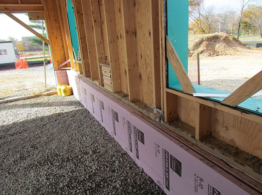
A wall section shows how everything connects—or fails to. Most Passive House walls start with cladding on a ventilated rain screen so water drains and surfaces dry. Behind it sits a weather-resistive barrier that shields the sheathing from bulk moisture.
The air barrier—often the sheathing itself—must run unbroken across foundations, floors, and roofs. Penetrations for fasteners and services get sealed with compatible tapes or fluid-applied membranes tested for airtightness. This continuous line is what keeps the pressure boundary intact and ensures the wall’s measured airtightness matches design expectations.
Thermal control depends on keeping continuous insulation outside the vapor layer so sheathing stays warm and safe from dew-point condensation. Designers calculate the exterior-to-interior R-ratio to keep vapor drive in check. Layer by layer—rain screen, WRB, air barrier, insulation, sheathing, framing, finish—it all has to act as one system.
These passive house wall construction details include the tricky parts—balconies, fasteners, window frames—that test every design assumption. Thermally broken clips hold cladding without cutting the insulation plane. Self-adhered membranes wrap window flanges into the air-barrier line so blower-door numbers stay tight when the test fan spins up.

Get the sequence right—air barrier first, then windows, flashing, cladding—and blower-door tests tend to go your way. A proven field approach uses 2×6 advanced framing with continuous exterior polyiso insulation installed over a taped sheathing panel. The air barrier lives at that sheathing layer, while the WRB and insulation handle thermal and moisture control.
This setup keeps framing inside the conditioned space and lets walls dry outward when they need to. In cold regions, thicker exterior polyiso can push total R-values past R-50 without ballooning wall depth. That’s the trade-off most builders prefer: a simple sequence that performs year after year.
No two climates—or crews—work the same. Performance depends on matching design intent to regional conditions and field capabilities.
In marine or mixed zones, vapor-open systems with exterior insulation allow outward drying and prevent trapped humidity. In cold zones, higher exterior-to-interior R-ratios keep dew points within safe ranges and maintain continuous thermal performance. Proper material selection ensures vapor balance and condensation control across all climate zones.
Constructability matters just as much as design theory. Crews experienced with standard framing adapt more easily to exterior insulation than to custom truss assemblies. Each configuration should be validated through PHPP energy modeling, WUFI hygrothermal analysis, and on-site blower-door testing. Infrared scans or embedded sensors verify that modeled performance aligns with real-world results.
The aim never changes: a wall that holds heat, manages moisture, and stays strong for decades through a well-detailed passive house wall assembly.
Rmax polyiso insulation boards deliver the thermal resistance, moisture stability, and code compliance required for Passive House construction. Installed as continuous exterior insulation, they minimize thermal bridges and protect sheathing from condensation while maintaining thin, efficient wall profiles. Contact us today for more information.
Every insulation project depends on consistent performance data—and that starts with clear material standards. The ASTM C578 specification defines how rigid polystyrene insulation is manufactured, tested, and classified by strength and density. Understanding these classifications allows designers and specifiers to select materials that meet both structural and thermal demands across roofs, walls, and foundations.
The standard is the Specification for Rigid, Cellular Polystyrene Thermal Insulation. It defines property requirements for molded or extruded foam boards used in building envelopes and civil applications. The document applies to insulation operating between −65 °F and 165 °F and excludes laminated or faced products that change base performance.
Originally issued in 1951 and revised many times since, it sets measurable thresholds for compressive strength, density, thermal resistance, dimensional stability, water absorption, vapor permeance, and flexural strength.
Manufacturers run controlled tests to prove compliance before a board can carry a specific “Type” label.
This framework promotes uniform minimum performance from one producer to the next, giving architects and contractors confidence that a specified type will meet identical minimum criteria regardless of brand.

Each type in ASTM C578 corresponds to a minimum compressive strength and nominal density, establishing predictable performance benchmarks for design and field use.Higher-density types generally resist crushing and moisture intrusion better, though actual moisture behavior also depends on manufacturing process and facers and may slightly reduce R-value per inch because of reduced trapped air. Designers typically balance compressive strength against budget and application—light framing rarely needs more than Type II, while plaza decks or freezer floors may justify Type VII or IX.
Each foam type defined in the specification must meet specific property thresholds verified through testing.
Compressive strength: Measured at 10 % deformation to verify load capacity for roofs or foundations.
Thermal resistance: Typically R-3.6 to R-4.5 per inch, confirmed by ASTM C518 testing.
Water absorption: Many boards limit absorption to low single-digit percentages by ASTM C272; some XPS products report values as low as 0.1%.
Vapor permeance: Determined separately by ASTM E96.
Dimensional stability: Most manufacturers design boards to maintain less than ~2 % change through thermal cycling, a common benchmark reflected in data sheets.
Flame and smoke index: Evaluated through ASTM E84 testing when required by building code or project specification; not a base requirement of the standard.
These benchmarks confirm that materials maintain mechanical and thermal integrity under load, moisture, and temperature variation. They do not guarantee system performance—installation and protection layers still determine long-term success.
Among all categories, ASTM C578 Type IV remains the workhorse grade. With a 25-psi compressive-strength minimum and moderate density, it balances rigidity, weight, and cost.
Type IV performs well in roof assemblies where insulation supports membrane loads without deformation and in below-grade walls subject to compressive and moisture stress.
It also appears in protected-membrane roof systems and insulated concrete forms, where compressive resistance helps limit deformation under long-term load.
Most designers call it the go-to spec unless a project pushes higher loads or unusual moisture exposure.
Its balance of strength and cost makes it the baseline EPS and XPS type for commercial and residential applications alike.

Both expanded polystyrene (EPS) and extruded polystyrene (XPS) comply with ASTM C578 but are produced differently. EPS is molded from pre-expanded beads fused in a block, producing uniform density with open cell interfaces. XPS is extruded in a continuous process, creating a tighter cell structure with lower water absorption.
XPS typically achieves around R-5 per inch, while EPS commonly ranges about R-3.6 to R-4.2, with values varying by product formulation and temperature. XPS can experience minor long-term thermal drift as blowing gases diffuse, while EPS values tend to remain more stable over time.
XPS typically shows lower water absorption in short-term standardized tests, while field studies have found EPS can retain less long-term moisture in certain soil or freeze-thaw exposures.
EPS uses low-GWP pentane blowing agents; new XPS formulations are transitioning to similar chemistry.
Because the specification classifies by performance rather than manufacturing method, both materials share the same type thresholds but exhibit slightly different field behavior. Designers evaluate these trade-offs in context of cost, exposure, and project requirements.
When writing or reviewing specifications, confirm these elements:
Type designation: Identify both material and type (e.g., “EPS Type IV insulation complying with ASTM C578”).
Compressive and thermal values: Use tested data, not nominal marketing values.
Moisture exposure: Select higher-density types for below-grade or inverted roof use.
Compatibility: Verify adhesive and membrane chemistry with polystyrene.
Fire protection: Install within rated assemblies or protect with code-approved barriers.
The standard sets the baseline; actual performance depends on installation and environmental conditions. Proper drainage and protection boards extend service life and preserve R-value over time.
Misinterpreting the requirements of the specification often leads to recurring design and installation errors that are easily avoided with careful review.
Assuming all EPS or XPS perform equally without testing.
Treating “Type” as a quality grade instead of a minimum standard.
Ignoring long-term creep under sustained loads.
Mixing solvent-based adhesives incompatible with polystyrene.
Using foam boards intended for thermal insulation as structural components.
Recognizing these limits keeps insulation systems reliable through their design life and avoids costly callbacks.

While both standards test compressive and thermal properties, polyiso often achieves among the highest R-values per inch under standard test conditions—typically around R-6 to R-6.5, though performance varies with temperature and long-term aging (LTTR).
It generally demonstrates better fire behavior than many EPS or XPS foams because it is a thermoset material that does not melt or drip under heat exposure.
Polyiso boards are also engineered to maintain dimensional stability across a broad service-temperature range when installed in accordance with manufacturer guidance.
Designers commonly specify C578-compliant foams for below-grade and cold-storage applications, while choosing C1289-certified polyiso for continuous insulation in above-grade walls and roofs.
Understanding these differences ensures balanced assemblies that meet both energy-efficiency and fire-safety objectives.
R-Max engineers manufacture polyiso insulation systems tested to ASTM C1289, offering among the highest R-values per inch typical of rigid foam boards. These products help create energy-efficient building envelopes and provide reliable fire and moisture performance when installed within properly designed assemblies. Contact us today for more information.
Every structure interacts with water. When groundwater accumulates around a foundation or retaining wall, it exerts a steady outward force known as hydrostatic water pressure. This unseen load can compromise waterproofing layers, distort walls, and weaken the building envelope over time. Recognizing how hydrostatic water builds and behaves helps designers take control through sound engineering and tighter envelope coordination.
Hydrostatic pressure is the pressure exerted by a fluid at rest due to the weight of that fluid. In practical terms, water in the ground exerts a force against any surface that contains it. The equation P=ρghP = \rho g hP=ρgh expresses this relationship, where pressure equals water density multiplied by gravitational acceleration and the height of the water column.
It sounds minor until you spread that pressure over a full wall. Then the numbers get serious. For every foot of water depth, roughly 0.43 psi—or about 62 psf—of pressure develops. Ten feet of water can therefore create more than 4 psi, or 620 psf, on a foundation wall. That pressure adds up.
Several site and environmental factors combine to create hydrostatic water loads.
High groundwater tables, impermeable clay soils, or poor surface grading prevent water from dispersing naturally.
Heavy rainfall, snowmelt, or irrigation runoff can saturate the backfill and trap water along the wall.
In regions with limited drainage, even a short storm can elevate groundwater levels enough to create sustained hydrostatic water loads for days. When that water has no escape path, it exerts continuous pressure on every joint, membrane, and material layer it contacts. Capillary action moves moisture through pores, but hydrostatic pressure forces it through defects under sustained head. Even so, every assembly has to plan for the worst-case load.
Lateral pressure pushes inward on walls, creating bowing or hairline cracking. Upward pressure under slabs or footings can cause uplift and floor heave. Water infiltration through cracks or unsealed penetrations transports dissolved minerals, which crystallize as efflorescence and expand pores within concrete.
Moisture intrusion reduces insulation efficiency and can degrade adhesives or sealants not rated for submerged conditions. Understanding what hydrostatic pressure does to these assemblies is essential to designing systems that remain dry and stable for decades.
In design terms, hydrostatic pressure on a wall must be considered alongside soil loads and surcharge forces. Engineers use pressure diagrams to calculate combined effects on foundations. The value increases linearly with depth, meaning that each additional foot below grade adds proportional stress.
This linear increase guides reinforcement detailing and wall thickness at the base. Waterproofing professionals likewise reference ASTM D5385, the standard test for hydrostatic head resistance, to ensure membranes and coatings can withstand realistic field conditions. These standards turn abstract physics into measurable construction criteria.

Drainage comes first. Hydrostatic water control starts there. Footing drains, gravel backfill, and perforated piping systems remove groundwater before it accumulates. Drainage boards create a vertical path for water to travel downward instead of pressing against the wall. Proper grading at the surface diverts runoff away from foundations.
Each of these steps reduces static head and minimizes direct hydrostatic pressure on the structure. When site conditions limit drainage potential, design must assume full hydrostatic load and rely on structural and material resistance to maintain integrity.
Continuous insulation plays a significant role in maintaining performance under hydrostatic water exposure. R-Max polyiso insulation, with its closed-cell structure, resists moisture absorption and retains compressive strength when subjected to lateral loads.
When integrated with waterproofing membranes, it forms part of a composite barrier that both insulates and protects. Its consistent thermal resistance prevents cold-surface condensation that can amplify moisture migration. That coverage has to stay tight and continuous, or pressure finds its way in.
The relationship between hydrostatic pressure and insulation performance is both mechanical and thermal. Mechanically, water pressure increases the likelihood of joint separation or fastener movement if materials lack adequate strength. Thermally, saturated assemblies lose R-value and can accelerate freeze-thaw cycling.
By specifying rigid, closed-cell insulation that resists both compression and water intrusion, designers limit these effects. R-Max systems achieve this through dimensional stability and minimal water absorption, maintaining continuous performance even in high-moisture environments. That’s the trade-off — durability means detail.
Effective hydrostatic water management extends beyond product selection.
Detailing and sequencing are critical.
Insulation and drainage layers should be installed before backfilling to prevent voids or membrane damage.
Penetrations must be sealed with compatible materials tested for hydrostatic head.
Positive-side waterproofing, applied to the exterior face of the wall, provides direct resistance to groundwater pressure and is generally preferred for long-term durability. Where exterior access is limited, negative-side coatings may be used internally, but their performance depends heavily on substrate preparation and surface dryness.
Drains need routine flushing and verification, or pressure starts to creep back.
Settlement or hydrostatic shifts may alter groundwater pathways over time, changing load distribution on the wall.
Incorporating inspection ports or accessible cleanouts allows early detection and maintenance.
Managing hydrostatic pressure requires precise coordination among drainage design, waterproofing application, and continuous insulation placement. Drainage relieves pressure so membranes and structural elements carry less load, while continuous insulation maintains thermal stability under changing moisture conditions.
R-Max polyiso insulation supports this integration with closed-cell moisture resistance and high compressive strength. When drainage paths stay open, membranes remain sealed, and insulation remains continuous, the wall assembly resists both lateral water load and long-term degradation — turning hydrostatic pressure from a threat into a controlled design factor.

R-Max engineers design polyiso insulation to perform as part of a complete below-grade system. Its closed-cell composition resists moisture absorption, retains high compressive strength, and maintains thermal performance under load. Integrating R-Max boards with proper drainage and waterproofing systems helps protect structural integrity for the life of the building.
Contact our technical team today for specification guidance or design assistance.